Nice Tips About What Is The Normal Pitch Of A Breadboard

Decoding the Breadboard
1. Understanding Breadboard Basics
Ever looked at a breadboard and wondered what makes those little holes so perfectly aligned? It's all about the pitch, my friend! And no, we're not talking about a sales pitch. In the world of electronics, "pitch" refers to the spacing between those connection points. It's a fundamental characteristic that determines what components you can easily plug in and prototype with. Think of it like the spacing of train tracks; if it's off, things aren't going to run smoothly.
Why is this pitch business so important? Imagine trying to shove a component with wider pins into a breadboard designed for smaller ones. Not a pretty sight, and you risk damaging both the breadboard and your precious electronic parts. The standardized pitch ensures compatibility across a vast range of components, making prototyping a breeze. It's a quiet unsung hero in the world of DIY electronics projects.
The breadboard's consistent grid of holes isn't just there for looks. Each hole is carefully placed to accommodate standard electronic components. This allows for easy connections without soldering, using jumper wires to connect different components and build circuits. So, next time you see a breadboard, remember all the engineering that goes into those little holes and their spacing!
Also, you can think of the standard pitch as a universal language for electronic components. When manufacturers adhere to this standard, it guarantees that their products will play nice with breadboards. And that means fewer headaches and more successful projects for all of us tinkerers!

The Magical 0.1 Inch
2. Delving into the Standard Pitch
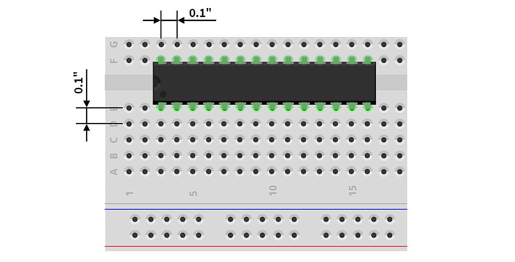
So, what exactly is the normal pitch of a breadboard? The answer is a delightfully simple 0.1 inches (or 2.54 millimeters). Yes, that's it! This seemingly arbitrary number is the bedrock of countless electronics projects. It's the Goldilocks of pitches — just right for a huge variety of components, from resistors and capacitors to integrated circuits (ICs) and transistors. It strikes a perfect balance between density and ease of use.
This standardized 0.1-inch pitch makes life so much easier. Without it, we'd be stuck trying to adapt components to fit mismatched breadboards, a tedious and frustrating process. Instead, we can confidently plug in our parts, knowing they'll fit snugly and make reliable connections. This is what makes breadboards so popular for prototyping and experimenting with electronic circuits.
The beauty of this standard pitch also lies in its longevity. It's been around for a long time, and it's still the dominant standard in the electronics world. This means that components designed decades ago will still work perfectly with modern breadboards. It's a testament to the foresight of the engineers who established this standard. They created a system that's both versatile and enduring.
Think about it: Every time you plug a component into a breadboard, you're participating in a grand tradition of standardized electronic design. You're building on the work of countless engineers and hobbyists who came before you. And it all hinges on that magical 0.1-inch pitch. Pretty cool, huh?

Why 0.1 Inch? A Look at the History and Rationale
3. Understanding the Significance
You might be wondering, why 0.1 inch? Was it just pulled out of thin air? Well, not exactly. The choice of 0.1 inch as the standard pitch wasn't random. It was carefully considered to accommodate the most common lead spacing found in electronic components at the time, especially dual in-line package (DIP) integrated circuits, which were becoming increasingly popular. This spacing allowed for easy insertion and removal of components without causing damage.
This pitch also lends itself well to manual assembly, making it easy for both professionals and hobbyists to work with. The spacing is wide enough to allow for the use of standard tools and techniques, such as wire wrapping and soldering (when not using a breadboard). The fact that it's a simple, easily measurable dimension also contributes to its widespread adoption. Imagine if the standard was something like 0.09375 inches — a real headache to work with!
The adoption of the 0.1-inch pitch standard also played a critical role in the development of integrated circuits themselves. Manufacturers designed their ICs with this spacing in mind, further solidifying its place in the electronics ecosystem. It created a virtuous cycle, where the standard pitch enabled the development of new components, which in turn reinforced the standard.
Ultimately, the success of the 0.1-inch pitch boils down to its practicality and versatility. It's a standard that has stood the test of time, adapting to the changing needs of the electronics industry while remaining easy to use and widely accessible. It's a testament to the power of good design and the importance of standardization.

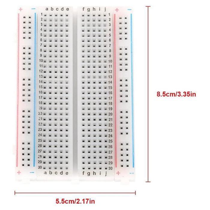
Jual Breadboard Mini Bread Board 400 Poin 400P Development Arduino
Beyond the Standard
4. Exploring Alternative Pitch Options
While the 0.1-inch pitch is the undisputed champion of the breadboard world, it's not the only pitch out there. You might encounter other pitch sizes, especially in more specialized applications. However, these are generally less common and often require adapters or custom solutions to work with standard breadboards.
For instance, some surface-mount components (SMCs) come in finer pitch sizes, such as 0.05 inches or even smaller. These components are designed to be soldered directly onto circuit boards and are typically not breadboard-friendly without the use of breakout boards. Breakout boards essentially translate the smaller pitch of the SMC to the standard 0.1-inch pitch of a breadboard.
Another example is certain types of connectors and headers, which may have different pitch sizes depending on their intended use. These connectors are often used to interface with external devices or to connect different circuit boards together. Again, adapters may be required to use these components with a standard breadboard.
The prevalence of the 0.1-inch standard is so strong that it's generally best to stick with components that adhere to this pitch whenever possible. It simplifies the prototyping process and ensures compatibility with the vast majority of breadboards and accessories. Unless you have a very specific reason to use a different pitch, sticking with the standard is almost always the best approach.

Circuit Diagram To Breadboard Examples
Practical Tips for Working with Breadboard Pitch
5. Tips and Tricks
Okay, so you know all about the 0.1-inch pitch. Now, let's talk about some practical tips for working with it. First off, always double-check the pin spacing of any component you're planning to use on a breadboard. While most through-hole components adhere to the 0.1-inch standard, it's always good to be sure. A quick measurement with a ruler or calipers can save you a lot of frustration.
When working with components that have multiple pins, such as ICs, be careful not to bend the pins excessively. Repeated bending can weaken the pins and make them more prone to breakage. If a pin is slightly bent, gently straighten it before inserting it into the breadboard. A pair of needle-nose pliers can be helpful for this.
For components that don't quite fit the standard pitch, consider using adapter boards or "dead bug" mounting techniques. Adapter boards provide a convenient way to interface with components that have different pin spacings, while "dead bug" mounting involves soldering the component upside down and using wires to connect to the breadboard.
Finally, remember that the 0.1-inch pitch is just a starting point. As you become more experienced with electronics, you may find yourself experimenting with different component types and mounting techniques. The key is to understand the underlying principles and to adapt your approach to the specific requirements of your project.
